LiPo Batteries and more!

Today, we finished our experimentation and verification of our new power supply. Previously we were using 16AA batteries to power the system. 8AA (8*1.5V = 12V) were for the Kinect, and 8AA going through a LM7805 voltage regulator which stepped the voltage down to 5V for the BeagleBoard xM and mbed.  We had to use this set up since the LM7805s were readily available and we could not get 5V from AA batteries. Unfortunately, this set up had many setbacks:

  • added a lot of unnecessary weight
  • required the use of a very large and dangerous heatsink — the LM7805 could handle 1.5A and our system used up to 2A
  • required us to fiddle with two power supplies to when powering and shutting down the device
  • AA batteries are expensive for the amount of time they lasted (approximately 30 mins)
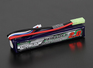
So motivated by these issues, we decided to switch to a slim 2000mAh, 3 cell LiPo battery that fits within the profile of the stripped down Kinect.
A 2000mAh, 3 cell LiPo battery delivers 11.V (3 * 3.7V) and can run at 2A continuously for an hour. Since our system averages less than 2A, it will last for over an hour on a single charge. Also, from our previous tests, we have verified that the Kinect — which is rated to work at 12V — will function as low as 8.5V. Not everything is perfect, however. We still need a voltage regulator to get 5V for the BeagleBoard and LiPo batteries require much more care to ensure they do not get overcharged or over-depleted.
For our new voltage regulator, we are using a more robust component that can take from 6-23V and output 5V at a maximum of 3A. This will allow us to eliminate the heatsink and use power directly from the LiPo instead of having a second power supply.
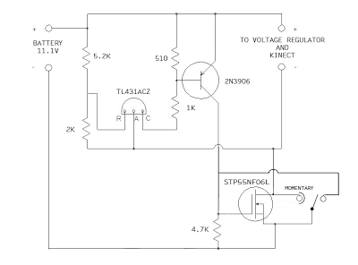
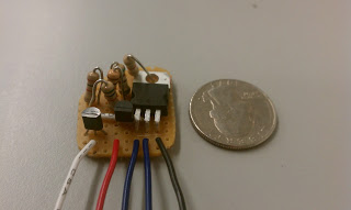
The final circuit we need for this system to work is a voltage cutoff circuit. Since LiPo cells lose their ability to accept a full charge if they are discharged beyond 3.0V, we need a circuit that cuts off power to the system when the 3 cell LiPo discharges to 9.0V (3 * 3.0V). Since this is the absolute limit, we built our circuit, with the help of Dan B., to cutoff at 9.5V. Dan’s circuit is operated by a single momentary switch that turns the device on, but no switch to turn it off. With our modifications, we will be able to operate the belt with a single (ON)-OFF switch — ‘ON’ in parenthesis indicates that the switch is momentary ON, static OFF. The circuit is shown below in schematic and PCB form:
Below is a video demonstrating proper function of these components, using a power supply instead of a LiPo to show the voltage cutoff.
PARTS LIST:
Battery
  • 2000mah 3S LiPo battery 15-25C — LiPo battery
  • Thunder-AC6-Charger-Power — charging station
  • LiPo guard charging bag — safety charging bag
  • Deans Ultra Connector Set — charging leads connectors
Voltage Regulator
  • 5VDC Voltage Regulator (BEC), Switch-Mode Type — 5V voltage regulator
Voltage Cutoff
  • STP55NF06L — power transistor
  • TL431ACZ — shunt regulator
  • 2N3906 — bipolar junction transistor, pnp
  • TIGC5B-6S-BL-NBL — switch option 1
  • SRN91-15BB — switch option 2
 

Team viSparsh

We’re almost ready to share some project updates, but in the meantime we wanted to share the final result of a group that we have been working with to replicate the Kinecthesia belt in India. Called viSparsh (a loose combination of ‘vision’ and ‘touch’ in Hindi), their team worked with us as part of the Young India Fellowship with UPenn. They successfully followed our blog to replicate our results, and with the help of a PandaBoard (instead of our BeagleBoard xM), they got it to work!
See their video demonstration below:
Great work guys!
viSparsh project blog: http://www.visparsh.blogspot.com/

Kinecthesia 2.0, Here We Come

First post in a while with a real project update!

BeagleBoard
For Kinecthesia 2.0, we will be using the BeagleBoard. “But you already are using the BeagleBoard!“, you say. Yes, but before, we were using the BeagleBoard XM, and now we will be downupgrading to the plain BeagleBoard. The BeagleBoard has multiple advantages for our project, but most importantly is its size. The BeagleBoard is 3″ x 3″ while the XM is 3.25″ x 3.25″. While this might not seem like a lot, it is actually a 15% reduction in area which, for a portable device, is not too shabby. This reduction comes with a reduction in processor speed, however. The BeagleBoard runs at 600 MHz compared to the XM’s 1 GHz. This should still be enough for the purposes of our device, while consuming less power!

Smaller Kinect
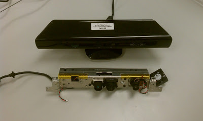
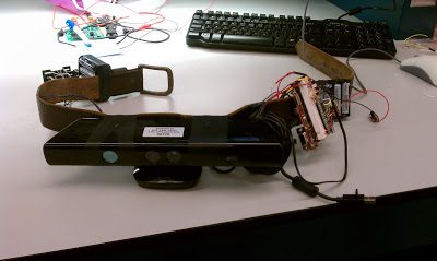
We also want to trim down the size of the Kinect because as you can see in the picture below, the Kinect is gigantic — too big for our device. Fortunately, there are plenty of how-to guides on how to tear down a Kinect. We borrowed a naked Kinect from Professor Mangharam’s lab and sure enough, it works great.


Building our own casing for the Kinect’s sensors will allow us have greater control of the design of the device while dramatically reducing weight and size. One option we have considered is to mount the processor and battery pack on the metal frame of the naked Kinect so that there are not bulky components all around the belt. The entire system (besides the vibrations motors which will still be around the waist) will all be enclosed in one case.

Update:
Stripped down Kinect specs:
length (without wings): 7 3/16 in
length (with wings): 9 1/2 in
height: 1 1/4 in
depth (without cameras): 1 3/16 in
depth (with cameras): 1 7/8
depth (with cameras and heatsink): 2 1/16 in
weight: 148 g


Kinect specs:
length (front): 11 1/8 in
length (back): 8 7/16 in
height (without base): 1 1/2 in
height (with base): 2 7/8 in
depth: 2 5/16 in
weight: 433 g


Kinecthesia version 1.0 weight: 1349 g (981 g without 16 AA batteries)


Better Vibration Motors
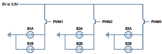
Our current system uses six vibration motors, however, we only have three vibration zones. Each zone has two vibrations motors working in parallel in order to increase the vibration sensation. We would like to replace these six buzzers with three stronger buzzers in order to reduce the complexity of the hardware. We would also like to change how the buzzers are mounted. Currently, the buzzers are mounted firmly to the rigid belt. This counteracts the forces of vibration and reduces the overall sensation. For increased sensation, the buzzers have to be able to move. We are experimenting with different ways to mount the buzzers, but one idea we are considering is mounting the buzzer on a wire or string (which is mounted to the belt) so it can rotate left and right around the axis of wire.

There are more updates to come, so stay tuned! Topics to look forward to: PWM on BeagleBoard, better obstacle detection, and reducing system delay.


New Video Overview

Below is the latest overview of the Kinecthesia project. Enjoy!


Download the video here.

Kinecthesia at Zeitgeist Americas 2011

I’m proud to announce that our project was chosen for Google Zeitgeist Young Minds! On top of that, I got to speak with Chelsea Clinton about Kinecthesia on the second day of the two-day conference which lasted from September 26-27, 2011. Here is the video:


Stay tuned for more Kinecthesia updates in the coming months…

New Name: Kinecthesia

Project Files, source code, and installation instructions are located here
Parts List
  • 16x AA Batteries
  • 2x 8 AA Battery Holder
  • LM7805 Voltage Regulator
  • 3x Heat Sink
  • Microsoft Kinect
  • Kinect USB Adaptor
  • BeagleBoard XM
  • mbed NXP LPC1768
  • Small circuit board
  • Logic Level Converter (BOB-08745)
  • 3x 1kΩ Resistor
  • 3x 2N3904 transistors
  • 6x Vibration Motors (buzzers) (ROB-08449)
  • Belt
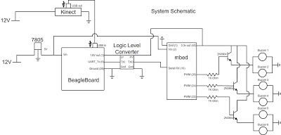
System Schematic
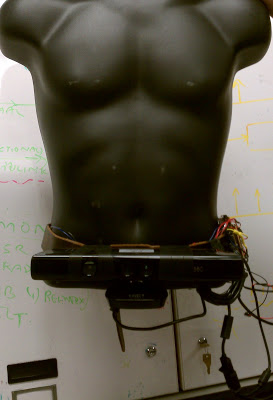
Final Version

Demonstration Video

All Done!

After all night of working in the lab which included spending an hour debugging a disconnected microsd card, a broken kinect cable which led to an emergency run to Gamestop on 11th and Market, putting batteries in backwards, wires coming unplugged, putting -12V into our Kinect, shorting a 12V supply, and two broken mbeds, we are all done and it works surprisingly well.
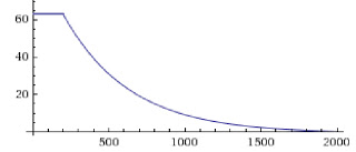
We tested our setup with three different buzzer intensity conversions. Two of our algorithms were linear, with one mapping our max depth from 0 to 63 and the other from 15 (~25% duty cycle, approximately the smallest pwm needed to feel a buzz) and our final one (the one we ended up using) was exponentially decaying.
We did this to give more emphasis to closer objects.
Our final demo consisted of our professor (Prof. Mangharam) navigating a room crowded with people with his eyes closed without touching anyone or anything.
tl;dr: Everything went better than expected.

Power Supply Issues

Up until this point, we have been powering our project from wall outlets. Our final project will be wearable and portable so battery power is a huge concern. We initially thought we could use a 11.1V LiPo 3000mAh battery, but we realized this might be overkill. If all we need is 12V, we can use a battery holder that can house 8 AA batteries. Since AA battery are 1.5V each, our total voltage will be exactly 12V (or close to it).

With this setup, our system worked but it wasn’t usable. Our 12V to 5V regulator made the heat sink feel like a stove, and the program ran for only 6 minutes before the voltage output hit 8.3V (the operating limit of the Kinect). Adding another 12V AA battery pack in parallel would increase how long it lasted but it would help our heat issues. Additionally, this method wastes batteries because the BeagleBoard, and mbed can still run after the battery hit the 8.3V mark.

To fix this issue, we first tried separating our power supply into two battery packs, 12V and 6V. The 12V pack worked well with the Kinect, but the 6V pack had too low of a voltage for our voltage regulator to work. Instead, we considered using a diode to to drop the 6V supply to 5.3V which would have worked for the BeagleBoard and mbed, but we didn’t have diodes that could handle the ~1.5A that the BeagleBoard and mbed needed.

For our final solution, we used two 12V AA battery packs. One was connected to the Kinect, and the other was connected to the BeagleBoard and mbed through the 12V to 5V regulator.

It’s Friday… Gotta have my bowl, gotta have Serial

We decided earlier in the week that we were going to use serial communication to send data from the Beagleboard to the mbed. We finally got that working today.
We transmitted the serial data using the UART_TX (pin 6) on Beagleboard’s expansion header. Serial works on the Beagleboard by alternating voltage from 1.8V to 0V with each voltage corresponding to a 1 or a 0, respectively. The mbed’s UART_RX pin accepts voltages between 3.3V which represents a 1 and 0V which represents a 0. So, we had to amplify the voltage coming out of the Beagleboard to 3.3V otherwise, the mbed might not recognize 1.8V as a high signal.
We first made a test program in bash on the Beagleboard to see if serial data was even coming out of pin 6.
while true
do
  echo t > /dev/ttyO1
done
Generally, computers use /dev/ttyS* for serial communication, but Ubuntu on the Beagleboard uses the device ttyO* for serial communication. We did not know this for a while so we were looking into other options for communication.
When we ran this program, connected the Beagleboard’s TX pin to its RX pin (pin 8), and polled the /dev/ttyO1 device we saw that it was, in fact, printing a ‘t’.
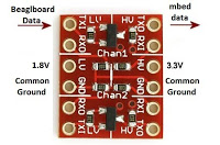
In order to send the signal to the mbed we first had to amplify to voltage. To do this, we used a logic level converter to shift the output voltage from 1.8V to 3.3V so that the mbed could recognize the data.
We then connected the TX signal out of the Beagleboard to the RX of the mbed (pin 10) to see if we could send data. We initially thought that the baud rate for the data was 115200 because that was the data speed for the RS-232 output of the Beagleboard. When we tested this, the mbed did not recognize the serial data sent in. We then switched the baud rate on the mbed to 9600 (the other most common baud rate) and it worked. We received a ‘t’ and were able to print the data sent from the Beagleboard to the mbed on a computer.
We then hooked up our Kinect to the Beagleboard, ran our program that parsed the depth data and converted the data into 3 bytes, sent that data out the TX pin of the Beagleboard, received that data on the RX pin of the mbed, printed it to the terminal, and had all of our buzzers buzzing at different levels.
We-we-we so excited
We so excited

Soldering the buzzers

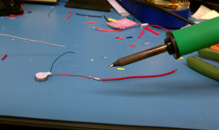
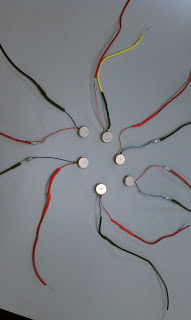
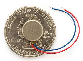
Before we can put together the entire Kinect-O-Vision 2000, we have to do something about the tiny wire ends that came on the buzzers. See the image below to get an idea of what I was talking about:


In the following two pictures, you can see the buzzers in the soldering process as well as the final product:


Kinect On Battery Power

We did some experiments with the Kinect after we split open it’s power cable. We hooked up the positive end to a variable power supply and the negative end to ground. We found that at 12V the Kinect operates and draws about 0.35A. We kept decreasing the voltage and we found that the minimum operating voltage for the Kinect is about 8.5V. At this level it drew about 0.42A. For all you Kinect hackers, the Kinect operates at under 9V!

If you want to power your Kinect wirelessly, just hook it up directly to 8 AA batteries and it will work just fine. The amount of time you get out of the AAs will vary with your use, but don’t expect something in the hours range.

Working late night at Kevin’s

Buzzers, Batteries, and BeagleBoard oh my! (also bigger microSDs)

Today, we decided on how we are going to implement each of the buzzers that lie on the waist of the user. We are going to write three bytes to the serial output of BeagleBoard (/dev/ttyS0) and read these values in the serial in of the mbed board (pins 9 and 10). The first two bits of each of these bytes will correspond to each of three buzzers and the other six bits will correspond to an intensity. This gives each buzzer 64(!) levels of granularity ranging from a 0% to 100% duty cycle. The mbed will read each of the values and adjust the pwm signal for each buzzer. Each buzzer operates at a max of 3.6V, but we have tested them up to 5V. The mbed has 5V and 3.3V outputs, so we will have to decide which pin to use in the future.
 
We also decided that we are going to use a 11.1V LiPo 3000mAh battery to power our entire system. We will use this to power the kinect and use 5V regulator with a heat sink to reduce this voltage to 5V for the beagleboard and mbed. LiPo batteries are lightweight and will power our entire system for a few hours before needing recharging.
Today we also upgraded our Beagleboard to run on a 16 GB MicroSD card which will make installing packages and compiling much easier.

Getting the Kinect to Play Nice with the BeagleBoard

We were a little skeptical at first about getting the Kinect to work with the BeagleBoard because we are working with ARM. Everything up till now was compiled for x86 for everything on the Kinect. Luckily the Kinect uses the standard USB library, so once we had the driver installed all the data could be read with relative ease.

We found another blog that outlined the steps we needed to follow in order to get the Kinect to work with Ubuntu 10.10. On the same blog in a post a few days later, we found instructions on how to install Kinect on the BeagleBoard.

Steps we took:

1. In the terminal install the required packages for Kinect

  sudo apt-get install git-core cmake libglut3-dev pkg-config gcc g++ build-essential libxmu-dev libxi-dev libusb-1.0-0-dev doxygen graphviz git

2. Create a new dir for Kinect files

  mkdir ~/kinect cd ~/kinect

3. Download and OpenNI from the git repo

  git clone https://github.com/OpenNI/OpenNI.git

4. Edit the make file in ~/kinect/OpenNI/Platform/Linux-x86/Build:

Comment out the lines:

  CFLAGS += -malign-double

  and

  ifeq ($(SSE_GENERATION), 2)
  CFLAGS += -msse2
  else
  ifeq ($(SSE_GENERATION), 3)
  CFLAGS += -msse3
  else
  ($error “Only SSE2 and SSE3 are supported”)
  endif
  endif

The -malign-double and -msse3 flags are only for x86 and will not work for gcc on ARM

5. Next install OpenNI

  cd OpenNI/Platform/Linux-x86/Build
  make && sudo make install

6. After this is done install the Kinect driver by giting (sp?) the sensor and Kinect driver git repo

  cd ~/kinect/
  git clone https://github.com/boilerbots/Sensor.git
  cd Sensor
  git checkout kinect

7. Finally install the sensor and Kinect driver

  cd Platform/Linux-x86/Build
  make && sudo make install

8. We did not have to install NITE, the middleware that allows for skeleton and gesture detection, because we are only processing raw depth data. If you want to install NITE see this blog.
All of the non-graphical examples will run, but any example with glut (an OpenGL command for displaying images on the screen) will seg fault. We have yet to find a way around this, but for our project, it is not necessary to see what the Kinect is seeing.
We only have around 86MB left on our 2GB MicroSD card after installing everything. In the middle of the Kinect installation we had to uninstall things in Gnome like the screensaver and audio applications so that the files could compile. Hopefully we do not need to transfer our information to a larger SD card…

Great Success!

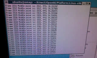
We just got the Kinect to work with the BeagleBoard-xM at 30 FPS! Details coming after I wake up.
 

Ubuntu 10.10 on BeagleBoard XM

The next step in our project was getting our BeagleBoard XM to run Ubuntu. We chose Ubuntu because it is the most lightweight operating system that we are familiar with that we think can interface with the Kinect. There is also a decent amount of documentation we found here that we used to give us a starting point.

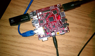
To start things off, we installed the pre-built image of the Maverick flavor of Ubuntu (10.10). We used Kevin’s Linux laptop which has an SD card reader to partition our 2GB microSD card, which the BeagleBoard uses to run the OS. We then unpacked the image, popped out the SD card and plugged it into the board. Hooking up the BeagleBoard to a TV via its HDMI port allowed us to use the terminal-based OS. Here is a picture of the BeagleBoard hooked up with wireless keyboard/mouse, ethernet, power, and HDMI:


The terminal got boring pretty quickly, so we decided to install GNOME which is a windows-based OS. Unfortunately, we needed an internet connection — this is where we ran into some trouble. Since the BeagleBoard XM does not have built in Wi-Fi, it couldn’t detect AirPennNet (but we realized it would be near impossible to authenticate it with AirPennNet via terminal anyway). We hooked up an Ethernet cable, but that didn’t work right away either. Finally, we decided to use my router as an intermediary between Penn’s closed internet system so that we wouldn’t have to both with registering a new device.

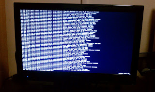
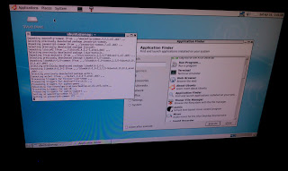
We figured out that before the BeagleBoard could access the Internet, we needed to manually enable network access which we found instructions for here. One weird thing we found after a few hours of tinkering is that the BeagleBoard XM calls its Ethernet port “usb1” and not “eth0” like we thought. Once we made this edit we could access the Internet. Here is a picture of the HDMI output of the BeagleBoard on my TV as we installed GNOME:


Next we installed a lightweight Internet browser, Midoro, and a text editor, gedit. Here is a picture of the GNOME desktop:


Our next step is to install the Kinect drivers!

Editing Sample Code

While testing the Kinect we came across a sample code segment called NiSimpleRead. This program took in the data from the Kinect and printed out the depth in the middle of the sensor. By editing the C# source file, we made a modified version that found the closest and furthest point in the Kinect’s view.
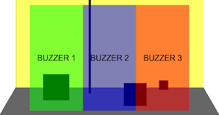
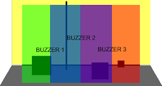
The next thing we did was try to figure out how to alert the user to a nearby object. We first thought about having the camera identify the closest object and buzz the respective buzzer based on the objects x-position. We then thought about dividing the vision into three segments for each buzzer. We could then find three of the closest points in each section and vibrate each buzzer based on the distance.
 
But, this would cause problems when an item was in between two zones. We eventually decided that the best way to determine which buzzer to buzz was by having the three zones overlap. Each buzzer would correspond to 1/2 of the Kinect”s view and each frame would correspond to a buzzer. We would then average the z-distance of each pixel in each of the buzzers frame and adjust the buzzers based on this average.
 
We programed the Kinect to report the average distance of each zone, but we cannot determine if this is the best method yet. We may have to weight the average if the object is closer to the middle of the screen, or if the object is lower. We will not know the best method of doing this until we have the entire system rigged up.
 

First tests with Kinect and PC

Before we started on the Kinect Belt, we wanted to mess around with the Kinect on our PCs. We found the instructions to install the driver from this website. While the set up was pretty easy, there were some kinks when it came to transferring files around to different folders like they instruct. Once Microsoft comes out with its official SDK, this should be a lot easier.


We were able to run all of the demos, but our favorite was the Ogre demo. The program maps points on your body to a stick figure around which is the body of a dual-sword-bearing ogre. Check out the video below:


As we wait for our parts to come in, we will continue testing and modifying code with the Kinect, and start to program the Kinect Belt.

Kinect Belt

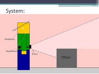
Our medical-themed project idea is called the Kinect-operated Vibro-tactile Belt for Aiding the Visually Impaired. As the name suggests, our product will use a Kinect to aid one’s vision. Our product will be aimed towards blind users.


Our plan is to mount a Kinect on a belt or waistband along with 3-6 vibration motors and a BeagleBoard. The Kinect will detect objects in the blind user’s path and vibrate the motors to warn elfrans.com/elf-viagra.html him or her of the obstacles. For example, if there is an obstacle on the left, the left most motors will vibrate.


The BeagleBoard will take input from the Kinect and output which motors to vibrate. We are still figuring out how to power it wirelessly, but this similar project should help us out.


Here is a diagram of our project which includes the headphones/voice guidance project expansion: